










A DC to DC charger takes the varying voltage coming from a vehicle alternator and converts it to the exact multi-stage charging voltage a second battery needs. It charges an auxiliary battery from a running engine, and it is not an electric vehicle charger. Two separate problems make it necessary: voltage lost over a long cable run, and modern alternators that never reach full charging voltage.
- A DC to DC charger is a buck-boost converter. It accepts an input that is too low or unstable to charge properly and lifts it to a regulated bulk, absorption and float profile matched to the battery chemistry.
- Voltage drop is the first problem. Over a seven-metre run at 40 A, 6 B&S cable, about 13.3 mm², loses about 0.72 V while 6 mm² cable loses about 1.61 V. A 13.8 V alternator can therefore deliver as little as 12.2 V at the battery.
- Smart alternators are the second problem. Delphi states that smart charging systems are ECU-controlled, vary output with demand and will not consistently reach 14 V. They appear on vehicles built to Euro 5 emissions standards or later.
- A LiFePO4 battery needs roughly 14.2 to 14.6 V to reach full charge, so a directly connected lithium battery stalls part-charged. It will also accept very high current, which can overheat an alternator that was never rated to supply it.
- Size the charger to the bank. Around 20 to 25 per cent of capacity is a sensible charge current, so a 40 A charger suits roughly a 160 to 200 Ah bank. Cable and fuse ratings follow from the current and the run length, and the caravan side of the installation must comply with AS/NZS 3001.2.
A DC to DC charger is a battery-to-battery charger. It sits between a vehicle starting battery and an auxiliary battery, and converts whatever direct current voltage it receives into a regulated charging voltage for the second battery.
The terms DC to DC charger, DC-DC charger, DC to DC battery charger and B2B charger all describe the same device.
What it actually does. It performs two jobs at once. It corrects the voltage, lifting a low or sagging input to the level the battery chemistry requires. It then applies a proper charge profile, moving through bulk, absorption and float rather than simply connecting the two batteries together.
What it is not. This is a 12 V or 24 V vehicle device for charging an auxiliary battery while the engine runs. It is unrelated to DC fast chargers for electric cars, which handle hundreds of volts and a completely different job. The shared words cause a lot of confusion when searching.
How it differs from a mains charger. An AC to DC charger converts 240 V mains power to 12 V and charges while you are plugged in at home or on a powered site. A DC to DC charger charges while you drive.
Most touring setups end up with both, and HiTech stocks each AC DC battery charger and DC to DC unit in the chargers and inverters range.
The same applies at 24 V. A 24 V DC-DC charger does the identical job on a 24-volt system, and the sizing and cable logic does not change.
If you want a second battery to reach full charge from the vehicle, yes. Why do I need a DC to DC charger is a fair question to ask before spending the money, and the answer is not brand loyalty.
Without one, a directly connected battery is limited by whatever voltage survives the cable run. On a modern vehicle, that is well below what any chemistry needs to finish charging.
There are two situations where you can skip it. The first is an auxiliary battery in the engine bay with a very short cable run on an older vehicle with a conventional alternator, where a direct connection may be adequate for a lead-acid battery.
The second is a battery only ever charged by solar or mains power, which needs a controller or a mains charger instead.
How a DC-to-DC battery charger works is easiest to follow in two stages. A DC-to-DC charger works as a buck-boost converter followed by a multi-stage charge controller.
The converter stage raises an input that is too low, or lowers one that is too high, to produce a stable output. The controller stage then decides what that output voltage should be at each point in the charge.
Here is the sequence from the moment the engine starts.
| Stage | What happens | Why it matters |
|---|---|---|
| Engine detection | An ignition sense wire or a voltage threshold tells the charger the engine is running. | Stops the charger draining the starting battery when the vehicle is parked. |
| Soft start | The charger ramps current up rather than demanding full output instantly. | Protects the alternator from a sudden load step. The HiTech 40 A unit lists soft start at 40 A. |
| Bulk | Constant current at the full rating until the battery reaches its bulk voltage. | This is where most of the capacity is replaced, and where charge current matters most. |
| Absorption | Voltage is held constant while current tapers off. | Takes the battery from roughly 80 per cent to full. Skipping it leaves the battery short. |
| Float | Voltage drops to a maintenance level. | Holds the battery full without overcharging it on a long drive. |
The charge voltages themselves depend on the chemistry you select. The HiTech 40 A DC to DC charger publishes a bulk voltage of 14.7 V for AGM and gel, 14.4 V for lead-acid, and 15.4 V for calcium, with a 13.5 V float.
Those numbers are not interchangeable, which is why selecting the correct battery type on the charger is not a cosmetic setting.
Where the input comes from. Most installations feed the charger from the tow vehicle through an Anderson plug. A dual input unit can also take a solar feed, and some switch between the two or blend them.
The HiTech unit accepts 12.4 to 16.0 V on the DC input and 16.0 to 25.0 V on the solar input, and delivers 13.5 to 15.0 V out at up to 40 A.
Conversion costs a little. Converting voltage is not free. A DC to DC charger is typically somewhere in the high eighties to mid nineties per cent efficient, so it draws slightly more from the alternator than it delivers to the battery. That conversion efficiency is a fair trade for a battery that actually finishes charging.

A direct connection fails for two independent reasons, and most explanations only cover one. The cable run loses voltage, and a modern alternator may never produce enough voltage to begin with. Either alone leaves the battery part-charged. Together they guarantee it.
Voltage drop rises with current and cable length, and falls as cable gets thicker. The figures below are calculated for a seven metre run each way at 40 A, which is a typical tow vehicle to caravan distance. Use the table to see why cable size is not a place to save money.
| Cable size | Voltage drop at 40 A over 7 m | What a 13.8 V alternator delivers |
|---|---|---|
| 6 B&S, about 13.3 mm² | About 0.72 V | About 13.1 V |
| 8 B&S, about 8.4 mm² | About 1.15 V | About 12.7 V |
| 6 mm² | About 1.61 V | About 12.2 V |
| 4 mm² | About 2.41 V | About 11.4 V |
Read the right-hand column against what the battery actually needs. A LiFePO4 battery requires roughly 14.2 to 14.6 V to reach full charge, and a lead-acid battery needs around 14.4 V.
Even in the best case here, with a heavy 6 B&S cable on a healthy conventional alternator, it arrives more than a volt short. The battery charges, but it never finishes.
That is the honest explanation for the most common complaint in caravan charging: the battery seems to work, the voltage looks plausible, and yet it sits at roughly half capacity after a long drive.
A smart alternator removes the assumption that the engine supplies a steady 14 V. Delphi, an alternator manufacturer, states that a healthy conventional alternator sits around 13.8 to 14.2 V, while smart charging systems are controlled by the vehicle ECU, vary their output according to demand and will not consistently reach 14 V.
Why they exist. A conventional alternator delivers full output whether the vehicle needs it or not, which burns fuel and raises emissions. Smart charging reduces output when the battery is already full and recovers energy during deceleration instead.
Delphi notes that smart charging systems are typically found on vehicles meeting the Euro 5 emissions standard or later, which covers Euro 6 vehicles too.
This is the part worth understanding. Variable-voltage alternators were not introduced to inconvenience caravanners. They are a consequence of emissions regulation, which is why a wiring approach that worked for decades stopped working on newer vehicles.
A DC to DC charger restores a predictable charge voltage regardless of what the alternator is doing.
Yes, and for lithium it is a safety requirement rather than an improvement. A LiFePO4 battery has very low internal resistance, which means it will accept as much current as the source will give it. Connected directly to an alternator, it can demand sustained high current that the alternator was never rated to deliver continuously.
What that risks. An alternator run at full output for long periods can overheat and fail. It is a far more expensive repair than the charger, and vehicle manufacturers commonly set conditions on what may be connected to the charging circuit. Check those conditions before wiring anything to the alternator.
A DC to DC charger solves this by current limiting. It draws only its rated current, so a 40 A charger presents a 40 A load and nothing more, whatever the battery would otherwise accept.
Match the charge profile to the chemistry. The second requirement is the charge profile. Lithium needs roughly 14.2 to 14.6 V and no float stage in the lead acid sense, which is a different profile from AGM or calcium. A charger must publish a LiFePO4 setting to charge lithium correctly.
This matters when choosing a unit. The HiTech (https://hitechpowersolutions.com.au/products/dc-to-dc-charger/) publishes profiles for AGM, gel, lead acid and calcium, which makes it a direct fit for those chemistries.
For a LiFePO4 bank, use a charger that lists a lithium profile, such as the integrated POWERSYNC 3050, which supports lithium, AGM, gel and lead acid depending on configuration. HiTech stocks LiFePO4 batteries from 100 Ah to 314 Ah in the battery management range.
Match the charge current to the battery bank. Around 20 to 25 per cent of bank capacity is a sensible target, which charges in a reasonable driving day without stressing the vehicle. On that basis a 40 amp DC to DC charger suits roughly a 160 to 200 Ah bank.
The practical choice is usually 25A, 40A or 50A. A 25 A unit suits a single 100 Ah battery, 40 A suits the common 200 Ah caravan bank, and 50 A is for larger banks or for owners who want the charge finished in a shorter drive.
Larger is not automatically better. A bigger charger draws more from the alternator, needs thicker cable and higher rated protection, and delivers little benefit once the bank is already charging faster than a typical drive requires.
A 100 Ah battery wants 20 to 25 A, a 200 Ah battery wants 40 A, and a 300 Ah battery wants 40 to 50 A. Those are the three answers most people are looking for.
Use the table below to carry the decision through to cable and protection. Bulk times assume the bank starts at 50 per cent and cover the bulk stage only, so allow longer for absorption to finish the charge. Cable and protection are sized for a seven metre run.
| Battery bank | Typical charge current | Bulk time from 50 per cent | Minimum cable at 7 m | Circuit protection |
|---|---|---|---|---|
| 100 Ah | 20 to 25 A | About 2 hours at 25 A | 8 B&S | 30 A |
| 200 Ah | 40 A | About 2.5 hours at 40 A | 6 B&S | 50 A |
| 300 Ah | 40 to 50 A | About 3.75 hours at 40 A | 6 B&S | 50 to 60 A |
| 400 Ah and above | 50 A or a second charger | About 4 hours at 50 A | 6 B&S or heavier | 60 A |
The HiTech 40 A unit is rated for battery banks from 120 Ah to 1200 Ah, which covers most single caravan installations. Very large banks are usually better served by an integrated system than by chasing charge current alone.
At the same current rating they are more alike than the marketing suggests. Compare published specifications rather than reputation, because the differences that matter are all printed on the spec sheet.
Most searches for this product carry a brand name. A Victron DC to DC charger, a REDARC DC to DC charger, whose units are often written as BCDC or bc dc charger, a Kings DC to DC charger and a Projecta DC DC battery charger all appear.
So do a Renogy DC to DC charger, an Enerdrive DC to DC charger and a Kickass DC to DC charger. They are all doing the same job, and the names are useful for telling models apart and nothing more.
Four figures decide whether a unit suits your setup, and every manufacturer publishes them.
Compared on those four points, a 40 amp DC to DC charger from one brand does much the same work as another at the same rating. That holds whether you are looking at a Kings 25amp DC DC charger, a Victron DC to DC charger 50 amp, or a Victron DC to DC charger with solar input.
The best DC to DC charger for a caravan is simply the one whose rating matches your bank and whose published profile matches your chemistry.
HiTech supplies and advises on the whole charging circuit from Somerton in northern Melbourne, which usually matters more than the badge on the case.
Size the cable to the current and the full run length, then protect both ends. A fuse or breaker belongs close to each battery, because either end can be the source of a fault.
Two sets of rules apply to the finished circuit. The caravan side falls under AS/NZS 3001.2, the standard for connectable electrical installations, and the tow vehicle wiring and trailer connection fall under the Australian Design Rules.
Anderson plug colours are not decoration. A grey Anderson plug on a caravan is the standard 50 A connector. A blue Anderson plug on a caravan, a red Anderson plug on a caravan, and the other colours use different mechanical keying.
That keying stops circuits running at different voltages being plugged into each other by mistake. Match the colour at both ends and keep the charging circuit on its own colour.
Caravan Anderson plug wiring is simple but unforgiving: heavy cable, correct polarity and a protection device on each side of the plug. An Anderson plug wiring diagram for a caravan and a wiring diagram from an Anderson plug to a caravan describe the same two connections, drawn from either end.
A DC to DC charger wiring diagram for a caravan is worth sketching before you buy anything, even roughly. Mark the two batteries, the charger, the Anderson plug and a protection device at each end.
Then measure the real cable route rather than estimating it. Most caravan DC to DC charger installation problems trace back to a run that turned out longer than expected.
HiTech stocks 50 A grey Anderson plugs and cable lugs in the wiring and connectors range, and 50 A, 80 A and 100 A manual reset circuit breakers plus Midi and ANL fuses in circuit protection.

Mount it in the caravan, close to the auxiliary battery, whenever the layout allows. The charger boosts whatever voltage reaches it, so putting it at the end of the long cable run means the drop happens before the correction rather than after it.
Mounting in the tow vehicle is still common, particularly where one vehicle tows several trailers or where there is no suitable space in the van. In that case, the cable from charger to battery carries the regulated output, so it has to be sized at least as carefully.
If the charger lives in an engine bay, check that it carries a suitable ingress protection rating for heat, dust and water. Check the published IP rating: an interior-rated unit does not belong under a bonnet.
A voltage sensitive relay simply connects the two batteries together once the starting battery reaches a set voltage. It does not convert, regulate or stage anything, so the auxiliary battery only ever sees whatever arrives down the cable.
That was adequate when alternators held a steady 14 V and banks were small lead acid batteries. It does not work with a smart alternator, which may never reach the trigger voltage, and it does not current limit for lithium.
A VSR relay or split charge relay has been superseded by the DC to DC charger for both reasons.
A DC to DC charger with solar input combines alternator charging and solar charging in one unit, managing both sources into a single battery bank. It suits anyone who tows and also camps off grid, because the two sources rarely arrive at the same time.
Why a combined unit helps. Driving charges the battery through the alternator. Sitting still charges it through solar. A dual input charger means one device, one set of settings and one charge profile rather than two controllers making separate decisions about the same battery.
The HiTech 40 A DC to DC charger takes a 16.0 to 25.0 V solar input alongside its 12.4 to 16.0 V DC input, at up to 40 A. If you are pairing a DC to DC charger with solar input and lithium, confirm the unit publishes a LiFePO4 profile before relying on it.
For a full system, the POWERSYNC 3050 integrates DC to DC charging, MPPT solar charging and a 3000 W pure sine wave inverter charger in one managed unit with centralised distribution and circuit protection. The POWERSYNC 3680 pairs a 2600 W inverter with smart charging and HiTech Connect monitoring.
No. There are three charging sources, and they do different jobs. The DC to DC charger handles charging while you drive, an MPPT controller handles solar while you are parked, and a mains charger handles 240 V when you are on a powered site.
A dual input charger merges the first two into one box. It still does not replace a mains charger. HiTech stocks MPPT solar charge controllers and solar panels for the solar side of that chain.
A dual battery system and a caravan DC to DC charging setup are the same concept described by different audiences. A dual battery system is the four wheel drive framing, usually a second battery under the bonnet or in a canopy. A caravan setup puts the auxiliary battery in the van.
The electrical problem is identical. A second battery has to be charged from the vehicle without draining the starting battery, without being limited by voltage drop and without overloading the alternator. Older dual battery systems used a VSR or an isolator. Current ones use a DC to DC charger for the reasons set out above.
The caravan case is the harder one, because the cable run is far longer. A dual battery system in a ute canopy might run two metres. A caravan run is commonly five to seven, which is exactly where voltage drop stops being a rounding error.
If you are researching a 4×4 dual battery system or a lithium dual battery system, the component list is the same one set out below. A dual battery system wiring diagram and a caravan charging diagram differ only in the length of the run between the two batteries.
A DC to DC charger on its own is not an installation. These are the parts a working charging circuit needs, and the order to decide them in.
| Component | What to choose | Why |
|---|---|---|
| DC to DC charger | Rated at roughly 20 to 25 per cent of bank capacity, with a profile for your chemistry. | Sets the charge current and the charge voltage. |
| Cable | Sized from current and total run length, not from habit. 6 B&S for 40 A over 7 m. | Controls voltage drop and heat. |
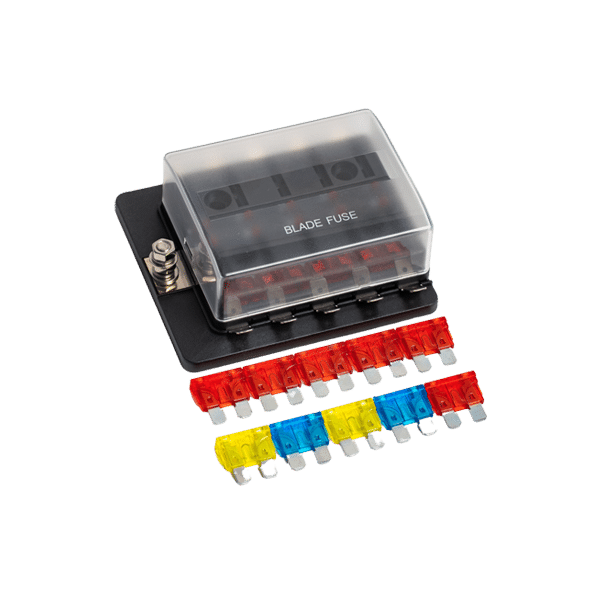
| Circuit protection | A fuse or breaker at each battery, rated just above charge current. | Either end of the run can be the fault source. |
| Anderson plug | 50 A grey for a typical caravan charging circuit. | Separates the charging circuit from the trailer plug. |
| Battery | Capacity matched to how you actually camp, with the chemistry the charger supports. | Determines charge current and run time. |
| Battery monitor | A shunt or capacity meter rather than voltage alone. | Confirms the battery is genuinely reaching full charge while towing. |
The last line is the one most setups skip. Voltage alone is a poor indicator of state of charge on lithium, because the voltage stays almost flat across most of the usable range.
Battery monitoring is how you find out whether any of the above is actually working. HiTech lists a 12 V battery voltage monitor and a battery capacity tester alongside the batteries in the battery management range.
Work out your battery chemistry and bank size first, because those two facts decide the charger. Chemistry sets the charge profile you must have, and capacity sets the charge current.
Then size the cable and protection from the current and the run length rather than guessing. That is where most underperforming installations go wrong, and it costs far less to get right at installation than to diagnose later.
Talk to the HiTech Power Solutions team about matching a charger, cable, protection and battery as one system, supplied Australia-wide from Somerton in northern Melbourne with free shipping on orders over \$100. Technical support can confirm the right charge current and chemistry profile for your setup before you buy.
Check the build date and look at the negative battery terminal. Delphi notes that smart charging systems appear on vehicles meeting Euro 5 emissions standards or later, and that these vehicles often carry a battery sensor fitted to the negative terminal. A workshop can confirm it by watching charging voltage vary while the engine runs.
Often yes, with care. How to install a DC to DC charger in a caravan is a job many owners take on, because the 12 V side is extra-low voltage and sits outside licensed electrical work. The work still involves heavy-current cable, correct protection at both ends and a connection to the vehicle charging circuit, where a mistake is expensive. An auto electrician is the sensible choice if any part of that is unfamiliar.
Divide the amp-hours you need to replace by the charge current. A 200 Ah bank at 50 per cent needs about 100 Ah, so a 40 A charger covers the bulk stage in roughly two and a half hours of driving. Absorption then adds time, so a full charge takes longer than the arithmetic suggests.
Around 20 to 25 A suits a 100 Ah bank. That is a 20 to 25 per cent charge rate, which refills a half-flat battery in about two hours of bulk charging without demanding much from the alternator.
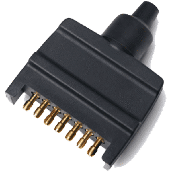
An Anderson plug is a high-current two-pole connector that joins the tow vehicle charging circuit to the caravan. You need one for any DC charging circuit, because a trailer plug is not rated for charging current. Knowing how to install an Anderson plug for a caravan matters less than getting the cable size and the protection at each end right.
No, provided engine detection is wired correctly. The charger only operates when it sees the engine running, either through an ignition sense wire or a voltage threshold, so it stops drawing once the vehicle is switched off.
Not for the solar itself, which needs a charge controller rather than a DC to DC charger. You need one as soon as you want the vehicle to charge the battery while you drive. A dual input unit covers both without a second device.

$215.00 Original price was: $215.00.$184.30Current price is: $184.30. + GST
Fill out the form below, and we’ll get back to you as soon as possible.
Dear Valued Customer,
We will be closed for operations from 19 December to 29 December.
All orders placed between 19 December and 29 December will be processed and delivered after 29 December.
Our technical team, communications team, and customer support will also resume contact after 29 December.
Wishing you a Merry Christmas and a Happy New Year!